Short story long, most 80's and 90's era game consoles used off-the-shelf integrated circuits for video/picture processing, and most of those integrated circuits generated RGB as well as composite video. As a result, even when the console manufacturers didn't bother to connect the RGB lines, RGB could still be enabled by tapping the RGB lines from the IC directly and connecting an amplifier to drive them. The best example of this is the Turbo Duo/PC Engine Duo.
When it comes to the NES/Famicom, things become a bit more interesting. Nintendo used a custom "PPU" chip to drive video, and as a result, RGB is not exposed, and can't simply be "tapped and amplified".
Enter the NESRGB. Rather than trying to tap RGB from somewhere on the board, the NESRGB actually hijacks the entire PPU chip. You literally have to desolder the PPU from the board and place a device in between it and the system. I mean, look at this thing, it's crazy.
|
|
NES RGB Mod - the whole light-green PCB in the middle with all of the wires coming off of it is the mod. It's about 1/3 the size of the whole mainboard!
|
My grasp of the science going on with this thing is somewhat rudimentary, but the gist of it is that the NESRGB board is intercepting certain signals from the CPU and generating its own picture in RGB space.
Which Console To Mod?
The NESRGB kit is pretty universal, so it can be applied to pretty much any version of Famicom/NES that I'm aware of. I made my decision based on two things.
1. I did not want to cut plastic. The NES does not have a suitable port to output RGB. The common solution to this is to add such a port. Classically this has meant drilling a hole and mounting a mini-din 8, but more recently this has shifted towards installing a multi-out matching the SNES/N64/Gamecube port to maintain compatibility with existing cables. While this is a good solution, it still involves cutting plastic.
2. The Famicom has additional sound capabilities not enabled in its international counterparts. I'm fuzzy on the specifics, but certain games contain their own sound chip used to add additional channels of "high quality" sound. There aren't a ton of games that have it but it's used by some major ones like Doki Doki Panic (the original game from which the western version of Super Mario Bros. 2 was made), Zelda No Densetsu (The Legend of Zelda), Akumajou Densetsu (Castlevania III: Dracula's Curse).
So I settled on the AV Famicom, because it's the only one of any of the versions of the console which already uses the Nintendo multi-out connector, and it happily happens to support the FM sound from the cartridge.
The Instructions
https://etim.net.au/nesrgb/installation-famicomav/
Tim Worthington - the guy who developed the NESRGB mod, has put up very nice instructions on his website. This is the most complex mod I've ever attempted in terms of invasiveness and the sheer number of points that have to be touched. For the most part the instructions are great. Just read them thoroughly...
RTFM
The first problem that I encountered was my own failure to read the instructions. One of the very first things you need to do after desoldering the PPU from the board is fitting an IC socket in its place. Before actually soldering anything together, you're advised to insert pin-strips into the adapter board and then plug them into the socket - by waiting to solder anything until it's all pushed together, you make sure the pins are properly aligned for when you need to unplug and replug the board into the socket later. The problem is that there are two different kinds of pin strips provided - round ones and square ones. You want to solder the round ones to the adapter board in this step, but the square ones come taped to the adapter board - which confused me. This took me a while to figure out but it was clearly spelled out in the instructions.
Palettes? What?
A palette in this context is the complete set of colors that the NES can produce. There are a total of 64 colors in that palette. Because the PPU is generating these colors internally in composite space there is no (good) direct translation to RGB. The actual values of those colors have to be reverse engineered. My understanding is a little fuzzy on what the specific challenges are but the short version is that games don't look right if the pallet isn't right, and it's difficult to get RGB to match the look of the original composite output of the NES. Because opinions vary on the correct approach, the NESRGB provides multiple options and comes with a switch which you can wire up to change between three pre-loaded palettes.
The Business End
The instructions are a little vague when it comes to wiring up video output connections and what cables to use.
TTL vs 75 ohm (What Cables You Can Use)
The instructions make reference to the need to use Gamecube SCART cables. This was not explained very thoroughly, but it basically comes down to the signal strength being driven on the output lines. My understanding of this is also somewhat limited but from what I've been reading,
TTL is a lower voltage output level, whereas "75 ohm" describes a higher voltage output level. The SNES outputs video at the higher voltage level, so it's necessary to add resistors and capacitors to the output lines to bring the signal back down to TTL before it gets connected to the display. Evidently the Gamecube outputs TTL, so the SCART cable made for it is a straight connection without resistors and capacitors - ergo the recommendation to use Gamecube cables. It seems like Tim had enough requests to accomodate 75 ohm output that the current versions of NESRGB default to 75 ohm output making them compatible with SNES cables. You now have to solder a jumper closed to change to TTL output.
I understand why 'TTL' is recommended/preferred - because it seems silly to ramp up the voltage, only to ramp it right back down at the plug end, but cable compatibility is more important to me so that's the method I went with.
Edit: Evidently my understanding of TTL was backwards. TTL actually refers to a higher voltage level - around 5Vpp (5 volts peak-to-peak) whereas ideal 75-ohm output is closer to 700mVpp (.7 volts peak-to-peak). Setting the output to TTL requires capacitors and resistors in the cable to pull the voltage down to the correct levels. If you output 75 ohm and have capacitors and resistors in the cable, you're needlessly diminishing the signal.
Sync
In one part of the instructions it vaguely refers to cutting the original composite video trace...or not. It doesn't really explain what this decision means - probably because this should be obvious. It was not obvious to me.
Firstly the point of this step is to disconnect the original signal path of composite video. I *thought* this was because the original composite video was still being driven and you don't want to push two signals at the same time. So the first time I tested this, I did so by just connecting the R, G and B lines and leaving the original composite video path intact. With a composite cable, the picture was the wrong color and missing elements. From some additional reading on the way the NESRGB works, there is evidently some "dummy" data being passed into the PPU to make it behave normally and I *think* that's what I was seeing - so while there was still a picture of some description, it definitely wasn't right.
Next, I
desoldered one leg of resistor R106 (this should have the same effect as cutting the trace but it's reversable) and then connecting the composite video line from the NESRGB to the output port. The result was a perfectly normal looking output with composite video cables.
When I tried to connect an RGB SCART cable to with just these four lines connected, it resulted in a wavy distorted picture, and it took me a little while to figure out why. (Hint: I was using a Sync-on-Luma cable).
In the instruction images you only see the R, G, B and Composite video lines connected, and this is exactly what I did.
 |
| From the instructions on Tim Worthington's Website |
I knew the wavy distorted picture was happening because of a lack of sync signal, but I didn't immediately understand why.
I had 3 different SNES SCART cables and I was fortunate enough that all three of them used a different method of obtaining sync - fortunate because one of them actually worked when I tested it, and that was the breadcrumb I needed to figure out what was going on.
If a video signal is a single long line of pixels, the sync signal is a timing pulse which explains to the display how to assemble it into a rectangle. One part of the pulse tells the display when to start the first line at the top of the display, the next tells it when it has reached the end of a line and to start drawing pixels on the next line down. This requires two types of signal - horizontal sync and vertical sync.
In composite video, the horizontal and vertical sync signals are mashed together with the color and light/dark information. In S-Video, horizontal and vertical sync are carried on the Luma (Y) channel along with the light/dark information. Pure RGB has the option of a separate conductor dedicated just to the horizontal and vertical sync - confusingly, this is called "composite sync" (c-sync). It's called "composite sync" because it is composed of both horizontal and vertical sync in a single signal, whereas composite video gets its name from the fact that it is composed of the color, light/dark and sync information all combined into a single channel.
Since the sync signal should theoretically be the same no matter how the video is being transmitted, it's possible for RGB to draw sync from other sources when c-sync isn't available. This makes for a total of three options for getting a sync signal for RGB:
Sync-on-Composite
The sync signal is taken from the composite video signal. This is the least desirable method because it involves sending the whole composite video signal through the cable. The composite video signal is "noisy" and can cause crosstalk with the other signals.
Sync-on-Luma
The sync signal is taken from the Luma (Y) S-video channel. This is a sort of middle-ground as it's cleaner than composite. It's sending less additional information that might cause crosstalk, but it's still sending some. It's necessary for systems that do not natively output c-sync (such as the original Playstation).
C-Sync
The dedicated sync signal is the cleanest way to get sync, but it's not necessarily available everywhere.
The NESRGB actually offers all of these connections, but the instructions showing only the four wires connected will only enable the worst quality option: Sync-on-Composite.
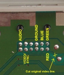
 |
| For reference: the Multi-out pins (Not an AV Famicom, but the pinouts are universal). Image taken from https://gamesx.com/wiki/doku.php?id=av:nintendomultiav |
To enable C-Sync, connect the "CS" on the NESRGB to pin 3 (labeled S/12V).
To enable Sync-on-Luma (and S-video), connect the "Y" on the NESRGB to pin 7 (labeled Y) and "C" on the NESRGB to pin 8 (labeled C).
In the end I needed to connect 7 conductors to fully enable all output options.
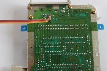
 |
Bottom of the mainboard. All connection options wired up.
From the Left:
Brown: Composite Video
Red: S-Video Chroma
Orange: S-Video Luma
Yellow: RGB Blue
Green: RGB C-Sync
Blue: RGB Green
Purple: RGB Red |
 |
| NESRGB end of the video out |
Using Different Palettes
Tim doesn't provide instructions on his website for using additional palettes (at least that I could find), but instructions are available here: http://www.firebrandx.com/nespalette.html
(Update: I did eventually stumble across a page on Tim's website which describes how to flash firmware and swap in new palettes, but Google seems to be the only way to reach it - I couldn't actually find where it was linked from on the site itself: http://etim.net.au/nesrgb/background_fault/)
Basically, you need to connect to a custom J-Tag header on the NESRGB and use a programmer like an Altera USB Blaster to reprogram the EEPROM with the new palettes.
I happened to have some JTAG sockets lying around. Since I'm not punching holes in the plastic, I just used a short segment of cable so the connector can be tucked inside the case. I'm not going to be flashing palettes all that often.
 |
| JTAG socket wired up for USB Blaster |
I also wired the toggle switch but left it internal in the case, covered in a plastic sleeve to make sure it doesn't cause any shorts. This does mean that I have to open the case to switch palettes, but again, I don't plan on doing so very often. With the amount of time and passion that FirebrandX put into his "Smooth" palette, I'm pretty sure I'm just going to leave it there, but it's good to have the option.
Final Thoughts
I'm pretty happy with the way this turned out. The installation effort basically took me an entire day, but that was mostly because I've never done it before, didn't really know what I was doing, and my desoldering tools left a lot to be desired. But the effort was well worth it. NES/Famicom games never looked so good. The main reason I did this was to be able to run it through the OSSC and play on a modern TV with perfect integer scaling, absolutely clean graphics and no perceptible lag, but it also cleaned up the image on my CRT displays. It blows the NES classic out of the water.