Monday, June 25, 2018

32X Squeal Fix

Backstory


Everything I do has a little story to go with it.  If you just want to know how I fixed the Squeal issue, skip to "Resolution" below.

I bought my 32X brand new when Sega had given up on the platform and the stores were liquidating them.  I think I paid about $30 for it, then took the free copy of Virtual Fighter out of the box, went across the street to a used game shop that hadn't yet caught on and sold Virtual Fighter for $35.  So essentially I got paid $5 to take the 32X off of the store's hands.

A Tale of 2 32X's

It's probably not a wonder then that I didn't have very high expectations of the 32X, and simply dismissed the video distortion and audio squeal it introduced.  I legitimately thought it worked that way.  At the time I only had a Genesis Model 1, so I misplaced the spacer that it comes with for use with the Genesis Model 2.  About 3 years ago I went to a local used game shop and bought a whole 32X for $25 just to get the stupid spacer so I could use it with a Genesis Model 2.  The newly bought 32X was scratched up and didn't look as nice as my original, so I put the newly bought one away and continued using the one I had bought new.

You Mean It's Not Supposed To Sound Like That?

Connecting the 32X to an OSSC greatly amplified and magnified the video noise and audio squeal to the point where it was damn near unplayable, so I started searching around to see if anyone knew how to improve the situation.  I found a lot of articles and a lot of supposition, but almost nothing in the way of a solution.  One thing stood out, however.  Some users were reporting that their 32X systems didn't add any audio or video noise at all.  That got me thinking, so I pulled out the 32X I had recently bought used and swapped it out for my shiny original, and I couldn't believe it.  There was no discernible audio or video noise at all!

Conjecture

So I had one "good" 32X and one "bad" 32X.  In all of my searches for a solution, three suggestions kept coming up, but there never seemed to be any followup on a solution.

1. Power

It was suggested in a couple of places that insufficient power was a possible cause.  In my case I have been using a "Trio M2" power adapter from www.retrogamecave.com.  I would expect that if the power supply was the problem, the problem would exist with both 32X modules, but it only affected the one.  I did try switching back to the original power bricks for both the Genesis 2 and the 32X, and also alternating, but there was no detectable difference.

2. Capacitors

The next thing that came up in a few places was the fact that the 32X had one particular "Low ESR" capacitor.  ESR is the resistance a capacitor has to being charged.  High ESR can cause odd failures because a capacitor may not charge up until after a delay, or the power supply may not be able to overcome the ESR to charge it at all.  At the time I didn't have an ESR meter, so I just shotgunned the whole module, replacing all of the capacitors with brand new ones, and making sure to use a "Low ESR" capacitor in the appropriate place.  This had zero effect on the squeal or the video distortion.

3. The Inductance Coil "L7".

The lengthiest discussions I came across involved this part.  The service manual hosted at Console5.com describes L7 as "CHOKE COIL 330UH LHL13TB331K".  There were a number of users reporting that they could actually hear the coil physically squeal directly from the console even with the audio output turned off.  This was not the case with me - I only heard the noise and saw the distortion through the AV output.  After reading through several discussions, and at least one user who swapped it out without any improvement, I decided to give it a shot, but also to keep my options open.
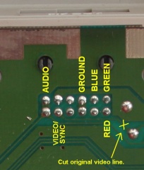
32X main board. The original L7 inductance coil circled.

The Plan

In addition to a direct replacement, I decided to try a couple of others to see if the problem was just poor component choice.

Mouser actually sells the exact part described in the service manual.

In reading its description the thing that really bugged me was that it was described as "unshielded".  It seemed reasonable to me that a shielded inductance coil might yield better results, so I looked for coils with similar attributes - focusing mainly on inductance value, max current and maximum DC resistance.

This one was pretty close:

This one was almost exact so I decided to try it even though it was the wrong package type (surface-mount rather than through-hole):


Today I finally got around to trying them out.

The first thing I did was to replace the original with the new LHL13TB331K.  It seemed like there may have been some small improvement, but the audio and video distortion were still terrible.

The next one I tried was the 994-RFS1317-334KL.  This was the shielded coil with a slightly lower DC resistance value, but was otherwise rated the same as the original part.  The footprint was too narrow to fit directly so I had to very carefully bend the legs of the coil to fit onto the board.  There was a definite improvement with this one.  The volume of the distortion was cut about in half, but it was definitely higher-pitched.  It was better but still awful.

Resolution

By the time I got to the 81-MBH12282C-331MAP3, my hopes were not very high.  Fortunately the vias had solder pads on the top of the board as well as the bottom so I didn't have to do anything too crazy to attach it.  There's an exposed ground point directly under the spot where the coil sits. This isn't a problem for the through-hole inductors, but would have caused a short on the SMD inductor, so I covered it with a tiny corner of black electrical tape before placing the new coil on top of it. There wasn't a lot of room to maneuver but I managed to get some good solid connections.  When I fired up the 32X for the first time I couldn't believe my eyes and ears.  It was dead quiet - not even a hint of the squeal or visual distortion.  For a moment I thought I may have blown out the audio circuit, but then the game started up clear as a bell.

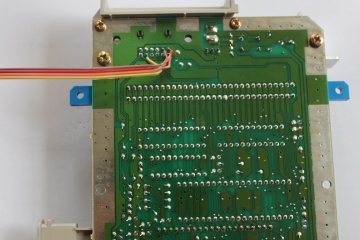
32X with the 81-MBH12282C-331MAP3 inductance coil installed as a replacement for L7 to fix audio squeal and video distortion.

Now I can obey Admiral Akbar, storm the imperial Death Star, and wipe out enemy fighters without distortion!

But Why?

Someone on the shmups forum challenged me to try to explain why this worked when the parts were technically the same.  My initial thought was that the new part was just "better", but the question made me consider other possibilities.  Before going into this I thought shielding might be the answer, but, then, of course 994-RFS1317-334KL did not eliminate the squeal.  Since it reduced the volume of the squeal, I'm inclined to think the shielding played a part, but it was definitely not the "smoking gun".

Possibility 1: Vibration
In my research I read that physical vibration is a factor with inductance coils.  At least one example corroborating this is the Turbo Express where the coils are covered in gray epoxy - presumably to dampen vibrations.

The shell of the LHL13TB331K and  994-RFS1317-334KL have a kind of skirt at the bottom that makes contact with the board in a circle all the way around the coil. When I first tried replacing the coil with the new LHL13TB331K, I tried to make sure to get full contact with the surface of the PCB, but in fairness, I was just eyeballing it. While it didn't appear to do much good it's possible it wasn't completely flush with the board and was allowing for vibration. With the 994-RFS1317-334KL, the legs were too far apart to fit through the vias for the original coil and putting right-angle bends in them prevented the skirt of the coil from making contact with the board at all. With the 81-MBH12282C-331MAP3 (SMD), basically the entire bottom of the coil is a conductor. I had to put a little triangle of electrical tape over an exposed ground point under the coil to keep it from shorting.  So the entire underside of the coil sits flush against the board with a piece of electrical tape serving as a cushion- it's possible that full contact and the additional cushion is allowing the PCB to absorb all of the the vibration and that's the real difference.

Possibility 2: Inductance Value
The other thing is the inductance variation between the parts. When I measured the original, and the LHL13TB331K replacement, they both registered 0.3mH. It isn't exact, but it's at the low end of tolerance. The 994-RFS1317-334KL measured 0.33mH - exactly as rated, and it _did_ seem to make an improvement. Since my component analyzer doesn't have an easy way to measure SMD parts, I used DMM probes to measure the MBH12282C-331MAP3 and got 0.36mH. I assumed the DMM probes were going to introduce a certain amount of inductance by themselves and that might be throwing the reading off so I dismissed the difference. But since the question was asked, I went back and measured the LHL13TB331K using the same probes and got 0.3mH - meaning that the probe wires weren't throwing the measurement off as I had assumed, and the SMD coil does have a significantly higher inductance value.

The LHL13TB331K is rated at 330uH with a tolerance of 10%, meaning anything from 297uH to 363uH _should_ technically be acceptable, and the MBH12282C-331MAP3 is still within this margin, but in practice at the opposite (high) end compared to the original part.  From what I've been reading about coils, this shouldn't make that big of a difference, but who knows?

So, to recap, although the MBH12282C-331MAP3 has the exact same ratings as the original coil, it's also shielded, has nearly 20% more inductance, and is almost definitely making better physical contact with the PCB.

I have no intention of fussing with that 32X any further now that it's working perfectly, but logically if you wanted to try fixing it without replacing the coil, you could try doing something to dampen the coil by fixing it to the board, like using a soft epoxy to fix the coil to the board.

Tuesday, June 19, 2018

3DO FZ-10 Rescue

The 3DO isn't a great platform.  It's also not a particularly bad one either.  I've only ever met one person who professed nostalgia for it (specifically the game "Twisted").  There aren't really any "killer app" games for it.  Supposedly its version of Need For Speed is superior to the Playstation version in some way (I never bothered investigating the rumor).  There are a handful of interesting games.  Star Control II, a couple of Wing Commander titles, "D", etc... Regardless it's still a great piece of gaming history and represents an alternate view of the way things may have gone.  Comparing it to the other consoles of its time, the best way I can sum it up is to say that the 3DO iterated where the Playstation and Saturn innovated.  Like the Atari Jaguar, the 3DO was more of an extension of the 16-bit arc rather than the start of a new 32-bit trajectory.

I'm in the process of getting ODE's for all of the platforms I can, and this was next on my list.  Optical Drive Emulators (ODE's) are all the rage in the retro gaming community right now.  Think of them like flash carts for your disc based systems.  The ODE either replaces or bypasses the spinning disc drive and loads games directly from solid state media like SD cards or USB drives.

Attached to every review of an ODE is usually a sage treatise on the limited lifespan of optical drives and how they're getting rarer and rarer.  These drives have moving parts and that means friction which means wear, so logically they will eventually break down, but I think the notion that all optical drives are going to suddenly die enmasse in the next 20 years is just amateurish prognostication and sensationalist tripe.  I love these things because I can have the entire library (or at least large chunks of it) on a console at once. That's pretty much it.  I'm not worried about drives dying.

Someone going by MNEMO from Russia makes and sells a 3DO USB Host Controller.  The prices vary wildly, with one of the cheaper being the version for the FZ-10.  I once passed up an opportunity to buy an FZ-10 for about $50 when Best Buy was liquidating them. _Facepalm_  At the time I already had an FZ-1, and my impression of the FZ-10 was not good - if they reduced costs by replacing the tray loader with a lid mechanism, it seemed likely they cut corners in other aspects as well and to my mind, cheaper meant less reliable. The reality seems to have turned out the opposite as the FZ-10 is now pricier than the FZ-1 on Ebay.

What I needed was a cheap FZ-10, so I watched Ebay for broken "for parts or repair", and eventually this one popped up:

The only thing the seller reported wrong with it was the missing lid latch, but of course it "wasn't tested with any discs".  I asked the seller if the machine displayed an image when plugged into a TV and turned on.  He sent me a photo of the startup screen displaying, so we haggled on price and I got a pretty decent deal (about 1/3 of the going price of one in working condition).  I figured if the drive was toast, the console would probably still work just fine with the ODE.  The visible dirt on the outside of the console was a little worrisome, but I thought "how bad could it really be?"...

When the machine arrived the first thing I did was try to turn the spindle motor by hand.  It barely turned and felt like it was grinding - probably a lost cause.   Next I opened the case up and took a look inside.  I found a couple of splashes of mud on the PCB, the lid switch was stuck, and the CD drive mechanism was stuffed full of fuzz, hair and what looked like dessicated insect parts.  I removed the CD drive mechanism, and detached the spindle motor.  After giving it a good brushing with a toothbrush, I gave it a shot of silicone lubricant on the spindle shaft and after a turn or two, it spun freely.  After looking closely at the spindle, there's some kind of tension spring pressing against the shaft and I *think* that's what was gunked up.  So with the motor turning freely I thought I might have a chance of getting it working - as long the motor hadn't been burned out when it was seized up.

Next I disassembled the rest of the CD drive mechanism, cleaned each part with a toothbrush and naptha to clear away all of the grit and fuzz.  I also used soap and water on the plastic bits.  I carefully cleaned all of the existing grease from the laser transport rails, the laser and the gear teeth using a toothbrush and q-tips, then replaced it with a fresh application of lithium grease.  Once reassembled, I made sure to turn the grooved shaft that moves the laser mechanism by hand putting it all the way through it's range of travel, and sure enough it hung up part-way through because I had missed some grit in the groove, so I took it apart again, and used a stiff piece of paper to completely clean the groove, re-lubed everything and reassembled it.  This time it went all the way through its range of travel without getting caught.

Once the CD drive was back together, I gave all of the ribbon sockets a shot of Deoxit.  I also gave the lid switch a shot of it and moved it until it stopped sticking.  I took a lint-free swab and carefully cleaned the laser lens with 91% isopropyl. With the drive plugged back in, I plugged the 3DO into my monitor, popped a game disc in, turned it on, and to my utter surprise the CD drive came to life and loaded a game without a hitch!  I listened carefully for grinding noises or any other signs or damage or remaining grit in the mechanism, but if anything it sounded quieter and smoother than my FZ-1.  Let's see a first or second generation PS1 do that!

So at this point I had a fully working console, but what I could see of the motherboard was filthy.  I've seen "dirty" consoles before, but never one with actual dirt in it.  I say "what I could see" because about 2/3 of the motherboard is covered by a large thick RF shield.  Based on what I could see, I knew I wanted to take this thing outside and give it a good blow out with my air compressor rather than getting my workspace dirty, but when I unscrewed and removed the RF shield, this is what I found:

No, it's not what you're thinking - unless you were thinking it was two lovely mud dauber nests.  Somehow the minerals in the mud weren't enough to interfere with the proper operation of the console!  These nests were so solid that a full blast from my air compressor barely knocked any of them off.  I had to carefully peck and blast at it for about 15 minutes to get most of it off.  Once it got down to the last little bit I had to turn the motherboard upside-down over a sink, and scrub it off with distilled water and a toothbrush.  Holding it upside-down helped minimize spreading mud around the board.

After getting all of the visible mud off with distilled water, I gave it a good scrub with 91% isopropyl, and then a shot of naptha.  I used q-tips to spot clean any remaining filth, then sprayed the whole board with Deoxit to clear away as much of the oxidation as possible.

The bottom half of the console had evidently been submerged in water at some point as the RF shield was covered in huge splotches of rust, and the rust had embedded itself into the plastic of the case.  I soaked the bottom half of the case, including the RF shield in CLR for about 30 minutes then gave both a good scrub with an SOS pad, and a final wipe down with naptha.

With everything cleaned, dried and reassembled, I removed the spring from the door mechanism so it would stay shut without being clasped, popped a disc in and validated that I hadn't damaged anything while cleaning it.  As before, the game loaded immediately.  I played for about 30 minutes to make sure there weren't any overheating issues.

Since it's not in my nature to leave well-enough alone, I opened it back up to perform a 240p video mod on it which also went over without a hitch.
Externally mounted DPDT (On-On) switch to select 240p/480i.  Internally, pin 52 of the video encoder has been lifted from the board.  The center pole of the switch is wired to pin 52, the top pin is wired to pin 55 (55 is connected to Vcc so this pulls pin 52 high), the bottom pin is wired to pin 52's landing on the motherboard.


I found a replacement part for the clasp:
https://kpcomponents.co/products/cd-player-door-latch

That link is not the exact one I bought - I actually found one on Ebay that arrived more quickly but since Ebay removes listings after a certain age, it seemed pointless to link to it.  These seem to be pretty standard, though.  I've found many different listings for them, but I've only found them in one size.  Just search Google Images for "cd player lid latch" and you'll see half a dozen of them. Unfortunately I wasn't able to find a consistent part number or model number.  I did, however, find two other CD players in my house that happened to use the exact same connector so these are all over the place.  If you can't find one for sale, you might have luck going to a garage sale, Goodwill or some other second hand store and picking up a cheap CD player to cannibalize for the part.

Once I popped the spring back in and inserted the new lid latch, the restoration was mostly complete.
New generic lid latch installed in the FZ-10.  Works and looks original.

The only thing still missing was the plastic lens piece that the "ready" and "access" LEDs shine through.  Unlike the lid clasp, I didn't find any remains of the piece inside the case.
The lenses that catch the light for the Ready and Access lights were missing when I bought it.

The LEDs are bright enough that edges of the holes still light up green and red.  But unlike the lid clasp, the LED lens piece is clearly purpose made for the FZ-10 so the only way to get another one would be to cannibalize another 3DO.  After thinking it over for a while I decided on a solution. There's a rectangular bracket-like structure on the underside of the case, so I cut a piece of packing foam (the soft squishy kind that some monitors and TVs ship in now - I think it's the same kind of stuff that pool noodles are made of) to fit snugly in the bracket, then I covered the top of it with silicone sealant.

Foam piece with silicone sealant pushed up through the holes


Next I gently pushed it up into the slot so the silicone barely started to squish through the top.  The surface tension resulted in the convex curve like the originals had.
Not bad for a first attempt.  If I had used crystal clear silicone it would probably have been a nearly perfect match.

I let the silicone cure, then carefully augured holes in the foam under the opening to let as much light as possible shine through.  The result was pretty decent for a first attempt.  There are two things that would have made it better.  First, I should have used a silicone that would cure crystal clear.  I just used whatever I had on hand which turned out to cure a little white and cloudy.  Second, I should have made sure the top surface of the silicone was perfectly smooth before pushing it up into the holes.  There were streaks in it which are visible up close.  Had I done those two things I think this would have been indistinguishable from the real thing from the outside.

The result is not a perfect match, but it "works" and it's a lot better than open holes IMO.


After all that, it feels more like I've rescued an abused and abandoned puppy rather than refurbished a piece of Ebay junk.  I'm still blown away by the fact that this console is still working.  These things seem to be built like tanks.

Now all that's left is to get that USB Host Controller.  I've placed my order, but these things are (apparently) hand made and there's only one guy doing it, so it may be a long wait.

Wednesday, May 23, 2018

The road to Dreamcast 480p YPbPr

When I set up my current retro gaming area around 2013, I grouped the Dreamcast with the rest of the consoles of the generation it kicked off - the Playstation 2, the Gamecube and the XBOX.  That particular area has a dedicated CRT TV which natively supports all of the best resolutions those consoles have to offer.  Most games of the era max out at 480p, and all of those consoles have official support for 480p via Component/YPbPr except the Dreamcast.  The Dreamcast is absolutely capable of it, but until this week, all of my attempts to get 480p Component video out of the Dreamcast could be measured in degrees of failure.  If you just want to know how I finally did it, skip to the end. In the middle is the journey.

1999
The Sega Dreamcast was born during the earliest days of the transition from Standard Definition TeleVision (SDTV) to High Definition TeleVision (HDTV).  DVD was an up-and-coming technology which was driving the adoption of cleaner analog video technologies such as RGB and Component (YPbPr).  Though most households did not have the means to take advantage of those technologies in 1999, Sega seemed to be hedging their bets when they designed the Dreamcast's video output, and indeed some of the technology locked inside that little white box was well ahead of its time.

Interlacing
As consumer-level video technology improved in the late 90's in an arc towards HDTV, the first quality leap involved moving  from mixed signals such as Composite, to increasingly discrete signal transmission first with S-Video which separated color from brightness, and Component which separated brightness from color and the colors from each other.  The next step was the leap from "interlaced" to "Progressive Scan".  To thoroughly explain those terms would probably require several paragraphs, but I will spend a little time explaining the basic premise.  In an ideal and simple world, a television picture would be formed by drawing one horizontal line at a time from top to bottom until a whole frame was complete before starting over at the top to draw the next one.  Once upon a time in the early days of Television, engineering compromises were made.  I'm not entirely sure whether these compromises were made to cut down on bandwidth or to deal with slow cathode guns, but the engineers discovered that instead of drawing an entire screen from top to bottom, they could get almost the same effect in half the time and half the bandwidth by only drawing every-other horizontal line from top to bottom, starting over at the top and drawing the opposite lines from top to bottom.  So instead of drawing a whole frame at a time, they could draw a "field" of all of the even lines, followed by another "field" of all of the odd lines. Each field left gaps like the spaces between teeth in a comb, but when laid over top of each other, the "teeth" would mesh to exploit a property of human sight called "persistence of vision".  The screen was flickering so quickly as the teeth of the combs were interlocked, your eyes would sort of glue the two fields together and to your brain you would see a whole picture.  This is known as interlacing, and it's the reason that a SDTV image looks like it's bobbing up and down rapidly if you look at it up close.

Progressive Scan
Progressive Scan was sort of bringing us back towards that ideal state where an entire image is drawn top-to-bottom before the next one is displayed.  This has the effect of making the image appear more stable because it doesn't have the bobbing effect caused by alternating fields.  Actually, most 80's and early 90's game consoles tricked the CRT televisions into displaying a progressive image by always drawing odd or or even lines instead of alternating between them.  While this was never a ratified standard, it is commonly referred to as 240p, and it's what allowed those consoles to display a stable image on a TV that wasn't meant to do so - it's also what causes those characteristic "scan lines".  But when we talk about the turn of the century, Progressive Scan almost universally refers to 480p - which was a real ratified standard that not only created a rock solid image without flicker, but (arguably) doubled the horizontal resolution of the image.  The switch to 480p was a dramatic picture quality improvement, however it did not qualify as "high definition" because that term had been reserved for 720p and above. For this reason a new designation was given for this in-between format: Extended Definition TeleVision (EDTV) - a term that never really saw popular use.

In 1999 when the Dreamcast was released, progressive scan Televisions were on the horizon, but hadn't quite hit the market yet.  However almost every computer monitor available at the time did support progressive resolutions, so Sega's solution was to design a video output that could be configured to work with a PC monitor via a special adapter.  In 2000, I purchased one of these "VGA adapters" and connected my Dreamcast to a 17" PC monitor and I have to say the picture was unbelievably good - colors were more vibrant than ever, the image was razor sharp and lightning quick.  But a 17" PC monitor didn't really fit well in my gaming setup so I found myself falling back on the S-Video output to play on my television.

Consumer televisions capable of supporting 480p wouldn't be widely available until after the unfortunate demise of Sega's hardware business and therefore the Dreamcast.  So while all of the capabilities were right there in the Dreamcast, no one ever made official hardware to connect the Dreamcast to an EDTV to enjoy 480p on a larger screen.  While some early 480p televisions provided VGA inputs, it was hardly a common feature.

The Problem:
While the Dreamcast technically outputs everything needed to display 480p over component, some translation has to happen to make it work.  Firstly the Dreamcast has to be switched into "VGA mode" by grounding one of the pins on the AV out.  When it does this, the Dreamcast outputs video in a format called RGBHV - the "HV" part refers to the fact that horizontal and vertical sync pulses are delivered on separate channels.  However Component video requires a C-Sync which is the two pulses combined into a single channel.  The Dreamcast uses C-sync for everything else BUT VGA mode.  Activating VGA mode deactivates C-Sync.  So the next stage in the process needs to combine the H and V sync into C-Sync.  Lastly the color transmission needs to be converted from RGB to YPbPr.

My First Solution:
This was my first attempt at a Dreamcast 480p "box".
I hesitate to call my first solution a "success", though it did result in outputting 480p YPbPr from the Dreamcast to my TV, the picture was awful.

The first stage was the Dreamcast to VGA portion.  I initially used the Naki Dreamcast VGA adapter I bought back in the day but ended up buying a new Dreamcast VGA cable because the picture was too dark and I thought the box might be at fault (it wasn't). - what these adapters basically do is ground the "VGA Select" pin of the av-out and put the Dreamcast into VGA mode (RHBHV).

When I initially connected the VGA adapter to the VGA-to-Component adapter, the picture was very dark and hard to see.  Aside from trying another VGA adapter for the Dreamcast, I also ended up inserting a device called a "Gamma-X" as the second stage.  The purpose of this device is to boost brightness - and it did help, though not as much as I needed it to.

The third stage was a Monoprice VGA to Component YPbPr adapter.  There were several things wrong with this setup.  I lay most of it at the feet of the VGA to Component adapter.  The device was designed for maximum compatibility, not for the simple task I needed.  In order to always output a working 480p/720p/1080i/1080p signal, every single signal input was run through a scaler and the sync was regenerated.  This effectively crushed the contrast and introduced completely unnecessary scaling artifacts.

No matter what I did, I could never get the picture to look right.  Aside from not being progressive scan, the picture over S-Video looked waaaay better.

Forlorn Hope #1
Round about the time I was wrestling with this, the guys at HDRetrovision teased an image of a Dreamcast outputting 480p component video along with a blurb that they were in the early stages of working on a product that did exactly what I was looking for.  Unfortunately that was 2015 and as of the middle of 2018 they still haven't even really begun work on it.
The HD Retrovision cable that no one can actually buy.


Forlorn Hope #2
A couple of years ago I learned about The Behar Bros. (www.beharbros.com) - a couple of guys from Spain that produce a variety of output adapters for the Dreamcast.  They have several different types of boxes, including some that output directly to HDMI for a great signal on modern TVs.  They also make a replacement VGA adapter that will add artificial scanlines, and a simple sync-combiner etc...  Since most of their designs were clearly purpose-built for several different uses, I didn't think it would be unreasonable to reach out to them and ask if they could produce a box that just provided a straight-up 480p YPbPr output.  The first time I asked they were in the process of designing several new items and they told me to check back because they would soon have just the thing.  The second time I reached out about a year later, this is the response I received: "No, we don't have a component video solution. RGB is always better."  Not really, guys.

My Second Attempt
Emboldened by several recent successes in modding and a dawning understanding of circuit analysis, I decided that it would no longer be overly ambitious to think I could build my own adapter.  So I studied the problem for a couple of weeks, studied solutions to various pieces of it, made a plan, made a parts list, placed an order and got to work when it arrived.    My plan was to build my own sync-combiner and switch to throw the Dreamcast into VGA mode, but use an HDRetrovision Genesis Component cable to transcode the signal from RGBs to YPbPr.  It actually came together quite beautifully until I made a mistake and ended up burning out the HDRetrovision cable.  Not only are those things pricey, but it seems like it takes ages for them to be restocked.  That was a huge letdown, and i'm still not entirely sure what I did wrong - which tells me I still have quite a lot to learn.


My Final Solution
Simple Dreamcast VGA Cable

(Retrotek VGACTV1) VGA to YPbPr transcoder.


Amidst crying over my burned out HD Retrovision cable, I started re-exploring my options.  A lot has changed over the last few years since I started trying to do this.  I started by thinking I could use a sync-combiner that the Behar Bros. produced along with an RGB to YPbPr transcoder.

I'm currently using such a transcoder for my older 240p/480i systems, but I wasn't sure what 480p would do to it, and the seller had no idea either.  That led me to Retrotek on Ebay.

They sell a handful of specialty devices, including a RGB to YPbPr transcoder - which is what I went looking for in the first place, but somewhere along the line they also added a VGA to YPbPr transcoder they call the VGACTV1.

Unlike my general-purpose Monoprice adapter, this one is just a sync-combiner and transcoder - it doesn't do anything to scale or otherwise alter the resolution.  It does exactly what I had been trying to achieve all along.   The picture comes through sharp and clean with no obvious degradation at all - the Dreamcast is now a proper 480p console on my TV alongside its peers.

The Retrotek box is a little on the expensive side, but compared to how much I've spent over the last three or four years trying to make this happen and the fact that it not only works but works perfectly, it was a bargain.


Monday, May 07, 2018

Attempting to Explain RGB

A few years ago, I discovered the dramatic visual improvement from using RGB for my favorite classic game consoles.   The basics of this are often so basic that no one wants to take the time to talk through them because, duh, you should know this!  But I find it useful to rehash what I think is obvious for those corner cases when some nuance of explaining it helps someone to understand it where they couldn't before.

Why RGB is so great
Let's take as read that all analog video pictures are made up of dots (call them pixels or phosphor groups or whatever you like, they're a string of dots).  All color displays, regardless of technology - CRT, LCD, OLED, or whatever, have to separate picture information into discreet red green and blue values before they can assemble it into a screen full of colors.  All picture information starts as RGB and winds up as RGB, but the fewer transitions it has to go through along the way, the more faithful it will be to the original image.  RGB is pretty close to being the fewest transitions needed.

An Analogy:
Think of it like you have a mosaic picture made with thousands of red, green and blue painted marbles, and you want to move your mosaic to the other end of town.  The mosaic is too big to move all at once so you have to pack the marbles up, put them in a truck, drive to the other side of town and then reassemble the mosaic.  Let's say you only have one box to carry the marbles in, so you have to put them all into a big funnel that mixes them together.  In the act of mixing them together, the marbles rub against eachother scratching them and causing their paint to rub off on eachother so that now some of the green ones have red paint streaks and some of the blue ones have red paint streaks etc... When you get to the other side of town you have to sort them back out into red, green and blue using another hopper which also scratches them and gets some of them mixed up.  Now when you put the mosaic back together, the colors are recognizable but the picture is duller because all the marbles are scratched and some of the colors are smeared with streaks from other colors, and others are just in the wrong place.  That's the (grossly oversimplified) gist of how Composite video (the yellow RCA cable) works.  Now, if instead, you put the red, blue and green marbles neatly into their own separate boxes, when you got to the other end, you wouldn't have to scratch them or sort them, you would just simply reassemble them in the same order and the mosaic would barely be scratched all and every marble would be clean and in its proper place.  That's RGB.

Where RGB comes from.
RGB refers to the three primary colors - Red Green and Blue, of which all pixels on a color television are comprised.  By combining and using different values of these colors, a TV can produce a nearly complete spectrum of other colors. The values of these colors are also known as "saturation".  Irrespective of how it gets there, color information is separated into these three channels before being displayed on the screen.  In old school CRT displays this was because there were separate emitters for each of the three colors.  In LCD televisions this is because light is pushed through red green and blue layers of LCD, and the image processor needs to know how opaque to make each pixel in each LCD layer.

Brightness/Luma:
In addition to knowing the relative intensity of red green and blue, the TV also needs to work out how light/dark a pixel should be.  The relative brightness of a pixel is also known as its "Luma" value.  This is essentially the black white version of the picture.  In fact before color television, this signal was by itself.

Sync:
After figuring out what color and how bright a dot is, the TV needs to know where to draw it.
This is accomplished by something known as "sync".  The picture is transmitted as one continuous line.  Think of it like a machine constantly pushing out a colored string that's meant to be chopped up into pieces of a certain width and laid down one line at a time until it forms a rectangle that we'll call a "frame".  If we do our job right, the frame will be a picture of something recognizable.  But the machine doesn't stop moving, so as soon as we're done with one rectangle/frame, we immediately start snipping lines and drawing the next one.  We'd have to have some way of knowing precisely when a new rectangle was supposed to start, and when to snip the string to begin laying down the next line.  Suppose then that to help us along the machine spewing out the string also had two different with distinct sounds to them.  One whistle would blow when we were supposed to start a whole new rectangle, and the other would blow when we were supposed to snip each string and start a new line.  This is basically how sync works - one type of pulse tells the TV to begin drawing lines at the very top of the screen, the other tells it when to end the line and begin drawing on the next line down.  If that wasn't clear, I have one more analogy - think of it like a clock with hours minutes and seconds.  At the top of each hour, you begin drawing the screen at the top left corner.  Each movement of the second hand draws a pixel across the screen from left to right.  When the second hand reaches the top of the next minute, that's the signal to move one row down and begin drawing pixels from left to right again.  When you get to the end of the hour you've drawn a 60x60 grid of pixels.  Each movement of the minute hand is like an H-Sync pulse, and each movement of the Hour hand is like a V-Sync pulse.

A Tale of Two RGBs:
There is a 5-channel type of RGB known as RGBHV (Red, Green, Blue + Horizontal Sync + Vertical Sync) that was commonly used by personal computers and, if I'm not mistaken, some arcade monitors, but not really used by home televisions.  The RGB commonly used by game consoles in the 80's and 90's, and the topic of this article is also called RGBS (Red, Green, Blue + Sync) which only uses 4-channels.  The H and V sync channels are merged into something called "Composite Sync".  While RGBS was a common output format of retro game consoles and a common input format for consumer Televisions in Japan, Europe and Austrailia, it was not featured on consumer TVs in North America. (More on that below).

In a perfect world:
To ensure the best possible picture and the fewest transitions, it would be necessary to transmit all of the needed attributes of a picture on separate wires, or channels.  That would mean Red, Green, Blue, Luma, V-Sync and H-Sync for a total of 6 channels.  And that's all before you start talking about sound - can you imagine having to plug in 8 RCA plugs for a single device to get a picture and stereo sound?!  In a commercial sense, simplifying connections was much more important that image quality.  It didn't make any difference how awesome the picture quality was, if Grandma couldn't figure out how to hook up her VCR.  This led to a huge number of compromises.

RF Back in the Day
When analog TV signals were broadcast over the air back in the day, both the chroma and luma were combined into a single waveform (composite) and then modulated into a radio frequency (RF), and it was up to the TV circuitry to catch the radio signal, demodulate it back into a composite signal then figure out which part of the signal was originally luma and which part was chroma, then which part of the chroma was red, which was green, and which was blue.  The picture information was basically put in a blender and the TV had to sort it all out - problem is, it's impossible to assemble the original picture this way - just like the earlier analogy with the marbles only worse.  Each transition compromised the fidelity.  The colors appear smeared, sometimes light and color information is mixed, the sync signal had numerous errors and the result is a blurry semi-stable approximation of what the original signal looked like.

Composite
As TV technology advanced - particularly with the advent of the VCR, it became possible to skip the RF encode/decode by plugging a "composite" signal (the luma/chroma combined) directly into the TV - the standard marked by the yellow RCA connection.  Cutting out the RF modulate/demodulate step meant more of the original picture was intact and the result was a more stable correct image.  But the TV still had to guess about which information was luma and which was chroma, and then sift the chroma into RGB.

S-Video
While Europe, Austrailia and Japan began incorporating full RGB connectivity in their televisions by means of a standardized SCART cable, the standard was not adopted in the U.S.  Instead we were given an awkward half-way solution called S-Video, sometimes also referred to as "SVHS" for its association with the short-lived Super Video Home System videocassette standard for which it was seemingly created.  S-Video dramatically improved picture quality by separating Luma and Chroma into their own channels.  The TV no longer had to "guess" as to which part of the signal was light and which was color, and the result was a remarkable jump in image clarity.  The distinctiveness of the Sync signal from Luma made them very easy to accurately separate which also meant a super stable image.  The television still had to sift red green and blue values from a combined signal, but the improvement in contrast improved overall image quality so dramatically that many argued full RGB separation was ultimately unnecessary.

RGB(S)
RGB, as the name suggests keeps the color information separated into three distinct channels, with a fourth channel dedicated to C-Sync.  Each of the three color channels also carry Luma (lightness/darkness).  This is about as close as it gets to a perfect picture, but unfortunately it was never adopted as a standard for Televisions in North America.

Component a.k.a. Once Upon A Time in North America
And then things got weird.  When DVD started to become popular, it was clear that the pure digital format was capable of much higher fidelity than even S-Video could provide.  In countries using the SCART standard, this wasn't really an issue because that connector was perfectly capable of transporting the full spectrum of what DVD had to offer.  In the U.S. however we were wrestling with what to do about high definition content because we didn't have an existing connection type that would support it.  S-Video was insufficient, and the all-digital "firewire" being used by digital camcorders and specialty VCRs terrified the copy-averse MPAA.  While RGBS was perfectly equal to the task of both DVD playback and HD content playback, in North America we went a different way.  Instead of the decades old RGBS(Red, Green, Blue + Composite Sync) standard, we adopted something commonly referred to as "component" video, but more accurately described as "YPbPr" or "Color Difference".  (Component technically refers to any video signal where the colors are transmitted separately). Before getting into what that means, the important thing to know is that it is fundamentally incompatible with the already-existing RGBS signal standards in use and consequently supported by many older game consoles.

Component vs RGB
There's a lot of opinion out there about the image quality difference between RGBS and Component (YPbPr), but mathematically they produce images of identical fidelity.  Most opinions to the contrary are anecdotal and based on invalid test procedures.  You'll find a lot of people who think that RGBS is fundamentally superior to YPbPr, but they're wrong.  If anything, there's a slightly stronger argument to the contrary.  Ordinarily, combining color information into fewer channels involves modulating, multiplexing, or otherwise mashing it together to be sorted out later.  The clever thing about YPbPr is that it can effectively transmit three channels worth of data over two channels without compromising the fidelity of either by essentially using triangulation.  By knowing the difference between Blue and Green and the difference between Red and Green, you can mathematically figure out the exact original values of Red Green and Blue without any sifting or guesswork like what happens when Composite or S-Video gets untangled.  Another major difference between the two which is inconsequential in practice is the fact that each of them transmit Luma and Sync differently.  RGB uses a separate channel for C-Sync, whereas Component combines it with Luma.  All things being equal, this would seem to be an advantage for RGB, however sync is such a distinctive portion of the signal that, in practice, separating it from Luma can be done with nearly 100% accuracy (the only reason this isn't 100% is because nothing truly is).  On the flip side, RGBS carries Luma information over all three color channels, this part of the signal is completely redundant - the brightness of a pixel is not changed by its color value (saturation), so the Luma on each channel is exactly the same as that of the others.  While it's considerably easier to separate Luma from a single color than it is to separate Luma from a combined Chroma signal, this is still more error prone than separating C-Sync from Luma - thus the slightly stronger argument that Component/YPbPr can yield a more accurate picture.

Of course, all things are not equal, and the quality of your experience will definitely be more impacted by the quality of the source (game console, DVD player etc...), the quality of the cables (shielded/unshielded, quality conductors/cheap conductors), and the quality of the display (TV, monitor, BVM etc...) than it will by the differences between RGBS and YPbPr transmission methods.


Tuesday, March 27, 2018

Sega CD Model 2 Repair Notes

From time to time I like to fire up my disc based systems to keep the grease viscous and make sure everything is in good working order.  Well last night I fired up my Model 2 Sega CD and discovered that all was not well.

The disk tried to spin up and this horrible grinding and scraping noise came from the drive.  After several attempts the disk finally loaded, but it was painful and I shut it off immediately to prevent damage.  I managed to do some damage getting the silly thing apart, but everything is back in working order now.

Problem: Grinding

The grinding noise from a Sega CD Model 2 is evidently a pretty common issue.  There's a laser limit switch which the system uses to tell that the laser assembly has reached the center of the CD spindle.  Over time this switch stops working as desired.  The switch is essentially just two thin strips of copper inside a plastic shell.  When the sled touches the switch, the two strips are supposed to make contact and inform the mechanism to stop the motor.  Most people seem to think this switch gets bent out of shape from repeated use, and they will gently "bend" it back into place so it begins working again.  While that definitely works, I believe oxidation is also a factor, so I also used a pipette to drop a dab of Deoxit into the switch for good measure. 

Solution

Gently bending the limit switch "forward" for a few seconds and applying a drop of Deoxit cured the grinding problem.


Problem: Scraping

After I got everything back together and got the drive spinning again, I noticed there was a persistent scraping/scuffing noise.  At first I thought this was some issue with the magnetic clamp on the drive door.  (There's a circular magnet on the door which helps to lock the CD in place when the door is closed).  With the top of the CD unit removed and the magnetic clamp attached independent of the door, everything seemed to work normally, however when I reassembled it, the scraping persisted.  I eventually noticed that if I held the unit upside down while it was reading the disc, that the noise disappeared.  Upon closer examination, the CD drive landing was almost flush with the disc well.  This was causing the disc to scrape the well.  I noticed too late it was scratching the disc - my copy of Ecco Tides of Time now has a ring scratched in it :( It was also causing the magnetic clamp to scrape inside its assembly.  The problem was caused by the four rubber shock dampening grommets that hold the CD drive in place.  They were simply too old and had mostly collapsed, causing the CD assembly to sit too low.  Since I could not find replacements for them, I did the next best thing and rigged it.  

Solution

I cut some crude plastic washers out of some large heat shrink tubing and placed them on top of each of the four shafts that hold the drive in place.  This gave the collapsed rubber grommets enough support to lift the drive correctly. When it was reassembled the drive plane was now sitting about 2mm above the disc well, giving the disc plenty of clearance to spin freely.  In hindsight, I think leaving a disc in the drive may have contributed to the collapse of the original grommets, so I would recommend leaving the disc drive empty when not in use.


Problem: Door Switch

I'm not sure if this one is self-inflicted or not, but when I got everything apart, the door switch was twisted.  My recommendation here is to always take the top of the unit off with the door open.  Doing so with the door closed means that the top is contacting the door switch as you're working it off.  The reason I'm not sure if I did this was because the bend looked old, if that makes any sense.  

Solution

I ended up removing the clear plastic cover of the door switch and gently bending everything back into place. (To remove the cover you need to use a thin tool like a small screwdriver shaft to press the back of the cover forward while you pull it up away from the board).  It took quite a lot of trial and error to get it bent back to working normally again, so, like I said, always take the top off with the door open.


Problem: The System says "Checking Disk" but the drive is lifeless

This happened sort of in the middle of all of the troubleshooting and taking apart and putting back together.  The short version of the story is that the "Checking Disk" message appears when the system cannot communicate with the drive.  About the only way to tell this is what's going on is that "Checking Disk" stays on the screen even when the door switch indicates that the drive door is open (so it shouldn't be checking anything).  It took me a little while to figure out what had happened, but the system was extremely dusty when I disassembled it.  Evidently a piece of fuzz had gotten into the connector and was preventing good contact.

Solution

I ended up blasting the ribbon connector slots on both the mainboard and the CD drive with Deoxit and allowing them to dry completely (about 5-10 minutes).  After reconnecting everything the system started telling me to close the drive door again - which meant it was talking to the CD drive again.

Friday, March 16, 2018

Review: NESRGB Mod on an AV Famicom

Short story long, most 80's and 90's era game consoles used off-the-shelf integrated circuits for video/picture processing, and most of those integrated circuits generated RGB as well as composite video.  As a result, even when the console manufacturers didn't bother to connect the RGB lines, RGB could still be enabled by tapping the RGB lines from the IC directly and connecting an amplifier to drive them.  The best example of this is the Turbo Duo/PC Engine Duo.

When it comes to the NES/Famicom, things become a bit more interesting.  Nintendo used a custom "PPU" chip to drive video, and as a result, RGB is not exposed, and can't simply be "tapped and amplified".

Enter the NESRGB.  Rather than trying to tap RGB from somewhere on the board, the NESRGB actually hijacks the entire PPU chip. You literally have to desolder the PPU from the board and place a device in between it and the system.  I mean, look at this thing, it's crazy.


NES RGB Mod - the whole light-green PCB in the middle with all of the wires coming off of it is the mod.  It's about 1/3 the size of the whole mainboard!

My grasp of the science going on with this thing is somewhat rudimentary, but the gist of it is that the NESRGB board is intercepting certain signals from the CPU and generating its own picture in RGB space.

Which Console To Mod?

The NESRGB kit is pretty universal, so it can be applied to pretty much any version of Famicom/NES that I'm aware of.  I made my decision based on two things.

1. I did not want to cut plastic.  The NES does not have a suitable port to output RGB.  The common solution to this is to add such a port.  Classically this has meant drilling a hole and mounting a mini-din 8, but more recently this has shifted towards installing a multi-out matching the SNES/N64/Gamecube port to maintain compatibility with existing cables.  While this is a good solution, it still involves cutting plastic.

2. The Famicom has additional sound capabilities not enabled in its international counterparts.  I'm fuzzy on the specifics, but certain games contain their own sound chip used to add additional channels of "high quality" sound.  There aren't a ton of games that have it but it's used by some major ones like Doki Doki Panic (the original game from which the western version of Super Mario Bros. 2 was made), Zelda No Densetsu (The Legend of Zelda), Akumajou Densetsu (Castlevania III: Dracula's Curse).

So I settled on the AV Famicom, because it's the only one of any of the versions of the console which already uses the Nintendo multi-out connector, and it happily happens to support the FM sound from the cartridge.

The Instructions

https://etim.net.au/nesrgb/installation-famicomav/

Tim Worthington - the guy who developed the NESRGB mod, has put up very nice instructions on his website.  This is the most complex mod I've ever attempted in terms of invasiveness and the sheer number of points that have to be touched. For the most part the instructions are great.  Just read them thoroughly...

RTFM

The first problem that I encountered was my own failure to read the instructions.  One of the very first things you need to do after desoldering the PPU from the board is fitting an IC socket in its place.  Before actually soldering anything together, you're advised to insert pin-strips into the adapter board and then plug them into the socket - by waiting to solder anything until it's all pushed together, you make sure the pins are properly aligned for when you need to unplug and replug the board into the socket later.  The problem is that there are two different kinds of pin strips provided - round ones and square ones.  You want to solder the round ones to the adapter board in this step, but the square ones come taped to the adapter board - which confused me.  This took me a while to figure out but it was clearly spelled out in the instructions.

Palettes? What?

A palette in this context is the complete set of colors that the NES can produce.  There are a total of 64 colors in that palette.  Because the PPU is generating these colors internally in composite space there is no (good) direct translation to RGB.  The actual values of those colors have to be reverse engineered.  My understanding is a little fuzzy on what the specific challenges are but the short version is that games don't look right if the pallet isn't right, and it's difficult to get RGB to match the look of the original composite output of the NES.  Because opinions vary on the correct approach, the NESRGB provides multiple options and comes with a switch which you can wire up to change between three pre-loaded palettes.

The Business End

The instructions are a little vague when it comes to wiring up video output connections and what cables to use.

TTL vs 75 ohm (What Cables You Can Use)

The instructions make reference to the need to use Gamecube SCART cables.  This was not explained very thoroughly, but it basically comes down to the signal strength being driven on the output lines.  My understanding of this is also somewhat limited but from what I've been reading, TTL is a lower voltage output level, whereas "75 ohm" describes a higher voltage output level.  The SNES outputs video at the higher voltage level, so it's necessary to add resistors and capacitors to the output lines to bring the signal back down to TTL before it gets connected to the display.  Evidently the Gamecube outputs TTL, so the SCART cable made for it is a straight connection without resistors and capacitors - ergo the recommendation to use Gamecube cables.  It seems like Tim had enough requests to accomodate 75 ohm output that the current versions of  NESRGB default to 75 ohm output making them compatible with SNES cables.  You now have to solder a jumper closed to change to TTL output.

I understand why 'TTL' is recommended/preferred - because it seems silly to ramp up the voltage, only to ramp it right back down at the plug end, but cable compatibility is more important to me so that's the method I went with. 

Edit: Evidently my understanding of TTL was backwards.  TTL actually refers to a higher voltage level - around 5Vpp (5 volts peak-to-peak) whereas ideal 75-ohm output is closer to 700mVpp (.7 volts peak-to-peak).  Setting the output to TTL requires capacitors and resistors in the cable to pull the voltage down to the correct levels.  If you output 75 ohm and have capacitors and resistors in the cable, you're needlessly diminishing the signal.


Sync

In one part of the instructions it vaguely refers to cutting the original composite video trace...or not.  It doesn't really explain what this decision means - probably because this should be obvious.  It was not obvious to me.

AV-pinout2_small.jpg (19568 bytes)Firstly the point of this step is to disconnect the original signal path of composite video.  I *thought* this was because the original composite video was still being driven and you don't want to push two signals at the same time.  So the first time I tested this, I did so by just connecting the R, G and B lines and leaving the original composite video path intact.  With a composite cable, the picture was the wrong color and missing elements.  From some additional reading on the way the NESRGB works, there is evidently some "dummy" data being passed into the PPU to make it behave normally and I *think* that's what I was seeing - so while there was still a picture of some description, it definitely wasn't right.

Next, I desoldered one leg of resistor R106 (this should have the same effect as cutting the trace but it's reversable) and then connecting the composite video line from the NESRGB to the output port.  The result was a perfectly normal looking output with composite video cables.

When I tried to connect an RGB SCART cable to with just these four lines connected, it resulted in a wavy distorted picture, and it took me a little while to figure out why. (Hint: I was using a Sync-on-Luma cable).

In the instruction images you only see the R, G, B and Composite video lines connected, and this is exactly what I did.


From the instructions on Tim Worthington's Website


I knew the wavy distorted picture was happening because of a lack of sync signal, but I didn't immediately understand why.

I had 3 different SNES SCART cables and I was fortunate enough that all three of them used a different method of obtaining sync - fortunate because one of them actually worked when I tested it, and that was the breadcrumb I needed to figure out what was going on.

If a video signal is a single long line of pixels, the sync signal is a timing pulse which explains to the display how to assemble it into a rectangle.  One part of the pulse tells the display when to start the first line at the top of the display, the next tells it when it has reached the end of a line and to start drawing pixels on the next line down.  This requires two types of signal - horizontal sync and vertical sync.

In composite video, the horizontal and vertical sync signals are mashed together with the color and light/dark information.  In S-Video, horizontal and vertical sync are carried on the Luma (Y) channel along with the light/dark information.  Pure RGB has the option of a separate conductor dedicated just to the horizontal and vertical sync - confusingly, this is called "composite sync" (c-sync).  It's called "composite sync" because it is composed of  both horizontal and vertical sync in a single signal, whereas composite video gets its name from the fact that it is composed of the color, light/dark and sync information all combined into a single channel.

Since the sync signal should theoretically be the same no matter how the video is being transmitted, it's possible for RGB to draw sync from other sources when c-sync isn't available.  This makes for a total of three options for getting a sync signal for RGB:

Sync-on-Composite
The sync signal is taken from the composite video signal.  This is the least desirable method because it involves sending the whole composite video signal through the cable.  The composite video signal is "noisy" and can cause crosstalk with the other signals.

Sync-on-Luma
The sync signal is taken from the Luma (Y) S-video channel.  This is a sort of middle-ground as it's cleaner than composite. It's sending less additional information that might cause crosstalk, but it's still sending some.  It's necessary for systems that do not natively output c-sync (such as the original Playstation).

C-Sync
The dedicated sync signal is the cleanest way to get sync, but it's not necessarily available everywhere.

The NESRGB actually offers all of these connections, but the instructions showing only the four wires connected will only enable the worst quality option: Sync-on-Composite.


For reference: the Multi-out pins (Not an AV Famicom, but the pinouts are universal). Image taken from https://gamesx.com/wiki/doku.php?id=av:nintendomultiav

To enable C-Sync, connect the "CS" on the NESRGB to pin 3 (labeled S/12V).
To enable Sync-on-Luma (and S-video), connect the "Y" on the NESRGB to pin 7 (labeled Y) and "C" on the NESRGB to pin 8 (labeled C).

In the end I needed to connect 7 conductors to fully enable all output options.

Bottom of the mainboard.  All connection options wired up.
From the Left:
Brown: Composite Video
Red: S-Video Chroma
Orange: S-Video Luma
Yellow: RGB Blue
Green: RGB C-Sync
Blue: RGB Green
Purple: RGB Red


NESRGB end of the video out

Using Different Palettes


Tim doesn't provide instructions on his website for using additional palettes (at least that I could find), but instructions are available here: http://www.firebrandx.com/nespalette.html

(Update: I did eventually stumble across a page on Tim's website which describes how to flash firmware and swap in new palettes, but Google seems to be the only way to reach it - I couldn't actually find where it was linked from on the site itself: http://etim.net.au/nesrgb/background_fault/)

Basically, you need to connect to a custom J-Tag header on the NESRGB and use a programmer like an Altera USB Blaster to reprogram the EEPROM with the new palettes.

I happened to have some JTAG sockets lying around.  Since I'm not punching holes in the plastic, I just used a short segment of cable so the connector can be tucked inside the case.  I'm not going to be flashing palettes all that often.
JTAG socket wired up for USB Blaster


I also wired the toggle switch but left it internal in the case, covered in a plastic sleeve to make sure it doesn't cause any shorts.  This does mean that I have to open the case to switch palettes, but again, I don't plan on doing so very often.  With the amount of time and passion that FirebrandX put into his "Smooth" palette, I'm pretty sure I'm just going to leave it there, but it's good to have the option.

Final Thoughts


I'm pretty happy with the way this turned out.  The installation effort basically took me an entire day, but that was mostly because I've never done it before, didn't really know what I was doing, and my desoldering tools left a lot to be desired.  But the effort was well worth it.  NES/Famicom games never looked so good.  The main reason I did this was to be able to run it through the OSSC and play on a modern TV with perfect integer scaling, absolutely clean graphics and no perceptible lag, but it also cleaned up the image on my CRT displays.  It blows the NES classic out of the water.

Saturday, December 23, 2017

NeoSD NeoGeo AES Flash Cart review

In the 00's emulation was the rough draft of a love letter from technology to classic console gaming.  Emulation made it possible to play an entire library of console games with just a PC and a modest amount of know-how.  More than that, it provided a venue for fan localization of titles that were never released in our native tongue. I will never forget the hours I spent trying to get Final Fantasy V to play on my PC, or the hours I sunk into actually playing Seiken Densetsu 3 (Secred of Mana 2).  Console emulation is praiseworthy by the fact of its existence alone.  Be that as it may, emulation has always been an approximation of the original experience.  Even with the fastest and most powerful computers, emulation doesn't seem to be able to re-create the experience with complete fidelity - often it gets close enough to scratch the itch and it's a great deal better than nothing at all, but with input lag, screen tearing glitches and a whole other litany of nitnoid issues, emulation is far from an ideal way to experience the games of yesteryear.

In the '10's that love letter to classic console gaming seems to be more fleshed out with the advent of widely available flash carts for just about every console with a cartridge slot.  These cartridges allow you to play ROM images directly on original hardware - an experience indistinguishable, in practice, from playing the original cartridge.  Usually they work by inserting an SD card with ROMs into a specially made cartridge.  When the console is powered up with the cartridge there's usually a menu where you can select a game to play from the SD card and away you go.

Not all flash carts are created equal, and the relative sophistication of specific consoles can cause compatibility issues.  In general the systems which used their cartridge slot exclusively for data storage enjoy flash carts with high compatibility, whereas other systems which used the cartridge as an extension of the hardware itself have a bit rougher of a time.  For example the SNES used several "enhancement" chips, the "SuperFX" being the most obvious one. To date there aren't any flash carts that can simulate the SuperFX (though theoretically the SD2SNES might be able to one day).  


Another example of this is the SNK NeoGeo.  The NeoGeo was primarily an arcade platform which was extended to the home market.  The arcade version is called Multi Video System (MVS) and the home version is called Advanced Entertainment System (AES) except for additional copy protection applied to the AES versions of games the systems and software are identical. This is noteworthy because SNK emphasized function over mass market economy - i.e. they did whatever it took to make the games look and feel the way they wanted even if it wasn't cost-effective.  For this reason the NeoGeo sported some of the most audibly and visually impressive games of its time, and was the most expensive console of its generation.  The original retail price of some of the games sold for the AES were more than it costs to buy a whole PS4 system these days - and that's not even accounting for currency inflation.

The NeoGeo is a massively over-engineered system. It's like if, prior to the invention of the automobile, someone decided to make horse-drawn carriages faster by strapping a hot air balloon to the top to minimize friction, attaching a foot petal mechanism for the passengers to assist driving the wheels, and harnessing a dog sled team in front of the horses for additional pulling power. Whereas most flash carts just have to mimic a single ROM chip and feed a single bus, a NeoGeo flash cart would have to mimic multiple separate chips and feed 5 buses, which requires FPGAs (basically re-configurable circuits) which are not cheap. 

For this reason a lot of people had written off the possibility of a NeoGeo flash cart ever existing.  But true to the nature of the NeoGeo itself, pragmatism has proven to be no barrier to possibility.  After years of hearing that it couldn't be done, we've got not one but two flash carts for the NeoGeo.  The NeoSD came out late 2016 and has just picked up a U.S. distributor in June of this year.  And someone named "Darksoft" on atariage.com and arcade-projects.org is nearing completion on a similar and ostensibly even better NeoGeo flash cart.


While I initially wanted to wait for the "Darksoft" cart, the old adage "a bird in the hand is worth two in the bush" won out so I recently purchased a NeoSD and wanted to share my impressions. 

The product description really doesn't do enough(for me anyway) to explain why these carts are so expensive ($400-$500) and how they differ from flash carts for other systems, so I wanted to at least share a little of what I've learned before I explain my impressions. 

I'll try to relate my experience and impressions in relatively the order I experienced them.

Getting Games
Getting games for this cart was annoying. Unlike most flash carts where ROM sets are usually available in a single archive using a common format, NeoGeo games were primarily arcade games and this cart was developed to use MAME ROMS. My attempts to just get a complete set of NeoGeo games were stymied by the fact that MAME is not packaged that way - all of the ROMs for everything are in the same giant directory and there is no way to "filter by NeoGeo" when downloading. Mildly annoying is the fact that the ROMS have to be reformatted specifically for the NeoSD. However, the NeoBuilder software which performs this function provides two additional conveniences that kind of make the whole thing a wash. Firstly the tool verifies that the ROM you have will actually work - without exception every other flash cart I've used has had at least one ROM not load because the dump was wrong, or some snowflake artist decided to write his name on the splash screen and borked the checksum. It was nice to be forewarned that a ROM was not going to work so I could replace it. But perhaps the best thing about the tool is that it compares what you have against a set of known ROMs and tells you what you're missing so you can be assured of having everything. In the end I had to go to 4 different places to get a complete set that the NeoBuilder was happy with. I would mention them here but I have a feeling that it would get censored or fall afoul of some site policy. Assuming you're like me and don't already have a complete MAME ROMS lying around, one way you could approach it is: search for "Neo Geo Set Part", get those, run them through the tool, then find a MAME torrent and download just the zip files that match the names in the "missing" column. There will still probably be one or two that don't check out properly and you can just search for those specific zip files and try what's available until you get one that NeoBuilder likes. Also - a complete set of ROMs clocks in at around 10GB so a 16GB MicroSD is more than adequate.

Packaging
This is the first time I've purchased a "Complete Edition" of a flash cart from Stone Age gamer. The overall presentation is very nice. The design is nicely conservative and the included manual turned out to be really helpful. Was a little surprised that this one did not come with a Micro SD card, but I'm guessing the margins were pretty thin. While the custom case is cool and matches the aesthetic of North American AES games, for some reason they made the case the better part of an inch taller than the standard Neo Geo cases so it won't fit on the shelf next to my other Neo Geo carts. Were these cases actually made for something else and just happened to work for AES carts? Otherwise this seems like a bizarre choice. Each cart has a serial number which is printed on a sticker. On my cart this sticker was placed on the right side (opposite the Micro SD slot) right where the cartridge inserts into the AES, so one of the letters had been marred from scraping the side of the cart slot and I couldn't tell which letter it was. I don't know if it's that way on all of the carts or just mine, but that was also kind of a bizarre choice. Otherwise the cart shell is a very nice injection-molded piece. It doesn't feel quite as substantial as the real thing but it's close.

Firmware Update
The cart I was sent was not on the latest firmware. I noticed this when the included manual mentioned options that I didn't see when the cart booted up. The manual didn't include any instructions for this, but with www.neosdstore.com plastered on the splash screen it wasn't difficult to work out. Just go to www.neosdstore.com and click the downloads link. I think the developers are very worried about clone/copycat products because they require you to create an account and register your serial number in order to get firmware updates. The firmware update file itself has the serial number in its name, and I wouldn't be surprised if the serial number is embedded in the payload as well. Anyway, the update comes with instructions and I didn't have any issues with it.

Playing Games
So, after hunting down ROMs from several sources, converting them to the required format, copying them to a Micro SD and performing a firmware update I was ready to get my NeoGeo on.

When you power on the system you're presented with a list of games and some basic options mapped to controller buttons. One thing that confused me at first was the fact that there are two separate options menus. There's a systems options menu that you get by hitting "B" (I think), and there's a game options menu that you get to by hitting "Start" with the game highlighted.

What I liked:

-The Menu
The system menu was more robust than most flash carts I've used. Each game has an image of its title screen when highlighted (I believe these are embedded in the ROM for use with MVS) as well as a nicely formatted title for the game itself (It doesn't just use the ROM file name like most flash carts). From what I've seen, Darksoft's upcoming cart is going to be more involved, but the NeoSD is already more than adequate.

-The Options
As an AES owner without a hacked console (i.e. no UNIBIOS) I've basically always been stuck with the default settings on each cartridge. Since some of these games were designed to require a ton of quarters to complete, the difficulty coupled with the inability to add more credits made it impossible for me to fully enjoy them. By setting the BIOS mode to "MVS" on the system options menu, the game options menu now allows for "Soft DIP" settings and I can set unlimited credits, adjust the difficulty maximize lives etc... This is by far my favorite feature because it has made all of my games more accessible without requiring hardware modification to my console.

What I didn't like so much:
-Load Time
When switching between games, the system will go into an "erasing/writing" phase which can sometimes take minutes. There have been video comparisons of Darksoft's cart doing this much more quickly than the NeoSD for certain games, and, in fairness, the NeoSD loading certain other games more quickly than Darksoft's. My layman's understanding of this is that not only is some kind of flash NVRAM being re-written, but certain of the FPGA circuits need to be reprogrammed as well, so this all comes down to an unavoidable consequence of the NeoGeo's complexity. While it's completely understandable, it may come as a bit of a shock just how long you're required to wait to switch games - especially newer ones like Samurai Showdown V. Once the cart is programmed, loading is instant because the NeoSD basically becomes the game that you designated until you erase it and write another game to it. If you like you can even remove the SD card and set the NeoSD to boot the game directly so it behaves exactly like an original cart.

Conclusion
It has been a blast getting re-acquainted with my AES and trying out a ton of games I never had the opportunity to play before. While it's possible to play all of these games via emulation basically for free, nothing beats the responsiveness and presentation of the real thing. My wife and I have already spent about 12 hours this weekend playing old favorites, sampling random new stuff and just having an all-around great time with this. While Darksoft's upcoming cart will arguably be better in some respects, the NeoSD has everything I want or need from a NeoGeo flash cart and I'm very happy I went with it when I did.